Everyone uses the Internet, has a router, and usually connects to the network via Wi-Fi technology. But do you know how the connection actually reaches homes? Today, you will learn about the “magic” of high-speed communications.
What Proper Fiber Optic Network Installation Is
Fiber optic cable, the most commonly used conductor, is a glass tube through which a light signal is transmitted. Currently, it is the fastest commercial communication protocol. At the same time, it is the most complex and demanding.
Before you open a website, connect to an app, or similar – there is a whole cycle of preparatory work that you rarely notice. Namely:
- Route design.
- Preparation of the cable path.
- Fiber splicing (FTTH, PON, backbone).
- OTDR testing, attenuation measurement.
And, of course, the direct connection of the subscriber ONU, on-site equipment setup, network operation testing, and routing through the service provider. But this is the final and most visible part, so let’s focus for now on the background.

Route Design
The first stage is planning, and it is also the most difficult. Fiber is installed on aerial lines, that is, on utility poles. These poles already have electrical networks and equipment from other operators. Therefore, it is necessary to check the load, coordinate disconnections or install additional fixtures – this is all preparation.
This also applies to designing the fiber route for distributing optical signals to subscribers’ homes.
Cable Path Preparation
Special splitters are most often installed on poles, through which communications are distributed, connected in series or parallel. The installation of this equipment can sometimes be a challenging task, especially when coordinating with other providers.
Fiber Splicing (FTTH, PON, Backbone)
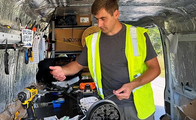
The most interesting part is splicing. This is exactly what Fiber Optic Splicers do. Here, not only the equipment matters, but also strict adherence to algorithms and technology. Any mistake – and the process must start over.
Even if everything seems perfect, problems can appear later, meaning one or several communication nodes may need to be redone.
OTDR Testing and Attenuation Measurement
At the final stage, an Optical Time Domain Reflectometer is used to check the line. The line length and other parameters are selected, and the attenuation coefficient is measured. A reading of up to 0.1 dB per splice is considered normal (on the screen, it looks like a “cardiogram,” where branches indicate splice points). If higher, it is necessary to return to the previous stage.
This is a brief description of the algorithm, which simply conveys the importance of each process. However, they do not always proceed smoothly – challenges and problems often arise, which we will discuss further.
The Complexity of Mass Connections: Technical Behind-the-Scenes
Individual fiber optic connections are rare. The reason is the complexity of the technical process. Just imagine that everything described above is carried out for each subscriber individually. The communication poles would be overloaded, and the fiber would hang like a spider web.
Therefore, it is now more common for a provider to service a specific area, prepare the infrastructure, and only then connect subscribers. This creates a number of challenges:
- Network branching (splitters, distribution boxes).
- Accounting for signal strength for each client.
- Coordination with other teams (electricians, installers).
We will focus on these in more detail.
Network Branching (Splitters, Distribution Boxes)

Each connection, each splice – this causes signal loss, delay, lower communication quality, reduced network speed, and so on. Therefore, the infrastructure is designed to minimize the impact of fiber optic limitations on the subscribers’ experience.
This is an extremely complex task that requires engineers’ maximum concentration and sometimes coordination with state authorities, local municipalities, representatives of community associations, and so on.
Accounting for Signal Strength for Each Client
A subscriber must receive a signal in the range of -8 to -28 dBm. If it is lower – the Internet will glitch or may not work at all. And yes, this becomes a problem, especially if too many clients are “assigned” to a single splitter.
In such cases, the structure has to be reworked, amplifiers installed, and multiple connection schemes tested. All this ensures that each subscriber receives what they are paying for.
Coordination with Other Teams (Electricians, Installers)
Since utility poles are public property, working with them requires special permits. And not only from the local government. It is necessary to coordinate with electricians, installers, and other providers to avoid damaging existing communications and safely lay fiber optic routes.
Installation Is Engineering, Not Just “Pulling a Cable”
The “magic” of the Internet is a combination of complex engineering, which includes:
- Terrain analysis, obstacle assessment, choosing the optimal route considering attenuation and accessibility.
- Accounting for fiber length, number of splices, and branches.
- Fiber splicing.
- OTDR testing, detecting defects, bends, breaks, and creating a network “map” for maintenance.
- Labeling and documentation.
- Coordination with other systems.
All this requires not only the coordinated work of specialized teams but also well-prepared engineering projects. So – no magic, only painstaking work to ensure that everyone gets their gigabits of network speed.
Also Read:

